THE
METERS
DESCRIPTION
The meter is a fully programmable ratemeter/ totalizer/ controller with
six-digit resolution for totalizing input pulses or rate measuring.
Alphanumeric display prompts make it easy to program with front-panel
buttons. You may use a personal computer to program the meter and monitor
the display data using the RS-232 option. You may store the program setup
in the nonvolatile memory for recall upon demand or at power-on.
The crystal timebase
is electronically calibrated. There are no internal adjustments and calibration
is done without opening the case. Available options include field-installable
dual-relay option card, RS-232 and analog output cards.
FEATURES
The following is a list of features:
* 6-digit, single input * Display of any engineering unit
* Front-panel scaling * 0.5 Hz to 30 kHz frequency inputs
* Signal conditioner standard for low level inputs
* DIP switch input selection
* Sensor excitation of 5, 8.2 and 12.4 Vdc
* Front-panel programmable as rate meter or totalizer
For more detailed information on meter features, refer to Tables 6-1 and
6-2.
MAIN BOARD
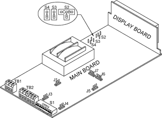
Table 2-2 details information for the S2, S3, and S4 jumpers. The S2 jumper
has 3 possible positions: A, B or C. Factory defaults are in bold and
italics. Figure 2-1 illustrates where these jumpers are located on the
main board.
Main
Board Jumpers Table 2-2
|
Jumper/
Switch
|
Position:
Installed
|
Description
|
|
S2
|
S2
S2-B
S2-C
Removed
|
Scale,
offset, setpoints and decimal points are unlocked. All else is
locked.
Everything is unlocked.
No lock-out, except for analog output parameters.
In the rate mode, meter shows "SPLO" and "SPHI" only (if
the relay option board is installed). In the totalize mode, meter
shows the OFFSEt, SPLO and SPHI - everything besides the relays
are locked out. In either mode, the meter stores changes in the
nonvolatile memory automatically. |
|
S3
|
S3-A
Removed
|
Enables
front-panel buttons.
Disables front-panel buttons. |
|
S4
|
S4
Removed
|
Enables
RECALL button. Disables RECALL button. |
* You must
install S5 in either the A or B position.
 Figure
2-1. Main Board
|
Front
of The Meter
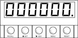
 Figure
2-2 Front-Panel
|
METER
DISPLAY
Digital LED display
-.9.9.9.9.9. or 9.9.9.9.9.9. 6-digit 7-segment, 0.56" high LED display
with programmable decimal point.
METER
BUTTONS
RECALL Button
To initialize (hard reset) the meter, press the RECALL and RESET
buttons simultaneously. The meter momentarily shows the program revision
letter and mode (totalize or rate). The meter then shows the last stored
(saved) program in the active (volatile) memory.
 SET Button
Press this button to modify the flashing function, number value or decimal
point (sub-menu only). For example, press the  SET button to toggle between the totAL (totalize) and rAte (rate)
modes. Once the correct function, number value or decimal point shows,
press the MENU button to enter the change into the active (volatile)
memory.
 ADV Button
Press this button to show the sub-menus and values for a selected menu
item. The meter shows values with left-most digit flashing. Press the
 ADV button
to move the flashing item from left to right through the digital display
and the ADV button
to move the flashing item from left to right through the digital display
and the  SET
button to change the flashing item's value. SET
button to change the flashing item's value.
MENU Button
Press this button
to show main menu items (refer to Section 6 for more information). The
meter does not show locked out (bypassed) items. The S2 and S3 jumpers
determine lock out status.
RESET Button
Press
this button to reset a latched alarm. Also, if you are in the totalize
mode, press this button to reset the counter and begin counting from
the offset. If you are in the setup menu (in either mode) the meter
returns to the run mode and makes measure-ments with the latest updated
menu items.
BACK
OF THE METER
Table 2-3
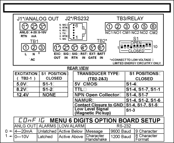
shows S1 positions for different types of transducer signals and excitation.
You may change default settings via the front-panel buttons.
S1
Dip Switch Positions Table 2-2
(Factory defaults are bold and in italics)
|
Transducer
Type (Connect to TB2-2 & TB2-3)
|
S1
Positions
|
|
5 V CMOS |
S1-4 |
|
TTL |
S1-4,
S1-1 |
|
NPN Open Collector |
S1-4,
S1-7 |
|
PNP Open Collector |
S1-4,
S1-6 |
| NAMUR |
S1-4,
S1-2, S1-6 |
| Contact
Closure to RTN |
S1-4,
S1-7, S1-5 |
| Contact
Closure to EXC |
S1-4,
S1-6, S1-5 |
| Low
Level Signal (Magnetic Pickup) |
S1-3 |
| Low
Level Signal When Average is Positive |
S1-3,
S1-4 |
|
Excitation
Output (Available on TB2-1)
|
|
| 5
V @ 50 mA max |
S1-2
Close |
| 12.4
V @ 100 mA max* |
S1-1
Close |
| 8.2
V @ 70 mA max* S1-1 |
Open
and S1-2 Open |
* Line voltage range
is limited to 115/230 ▒10% for excitation currents more than 50 mA.

Figure 2-3
Back view of the meter.
 WARNING: Incorrect
power input can damage the meter.
(Factory defaults: bold)
|
Jumper/
Switch
|
Status
|
Description
|
|
S1-1
S1-2
S1-1
S1-2
S1-1
S1-2
|
Open
Closed
Open
Open
Closed
Open
|
Excitation
output is set to 8.2 V
Excitation output is set to 12.4 V
Excitation output is set to 5.0 V
|
|
S1-3
|
Open
Closed
|
High
hystersis = 1.5 V.
Low hystersis = 20 mV. |
|
S1-4
|
Open
Closed
|
Threshold
is normal.
Threshold is shifted to positive. |
|
S1-5
|
Open
Closed
|
No low pass filter.
12 Hz low pass filter for contact closure. |
|
S1-6
|
Open
Closed
|
No pull-down resistor.
1.0 Kohm pull-down resistor. |
|
S1-7
|
Open
Closed
|
243K pull-up to +excitation.
3K pull-up resistor to excitation. |
|
S1-8
|
Open
Closed
|
Trigger edge = Negative (high to low transition).
Trigger edge = Positive (low to high transition). |
|
S1-9
|
Open
Closed
|
No signals internally connects to the input.
Twice line frequency signal internally connects to the input. |
|
S1-10
|
Open
Closed
|
Detects an ac power loss. (Refer to Section 3.3) Maintains
digital display during a dc power operation. |
|